How to Choose Automotive Oscillators for Your Application?
Choosing the right Automotive Oscillators starts with the job your circuit must perform. A timing source for an engine controller faces different demands from one serving an in-cabin display or a driver-assistance sensor. Frequency accuracy matters, but so do temperature drift, vibration, startup time, power use, and electromagnetic noise. The details can decide whether a design stays dependable through cold starts, long drives, and years of operation.
Timing expert John R. Vig writes, “The quartz crystal resonator is the most widely used frequency-determining element in oscillators.” His work offers useful context, though automotive selection requires more than choosing a crystal type. Compare the oscillator’s specified frequency stability with the full operating-temperature range, then check the datasheet’s vibration, aging, and supply-voltage limits. For example, a part rated for a narrow temperature range may look suitable on a bench, yet fall short near a hot engine bay. Verify qualification and test conditions; don’t assume similar part numbers mean identical performance.
Small checks matter. Confirm package size, output format, and load compatibility before committing the board layout. Consider how the clock interacts with nearby radios and high-speed interfaces. A tidy component table cannot capture every installation condition, and I would not treat a headline stability figure as a complete answer. This guide explains how to compare key specifications, weigh trade-offs, and match an oscillator to its real operating environment. The goal is a defensible choice—not a perfect one on paper.
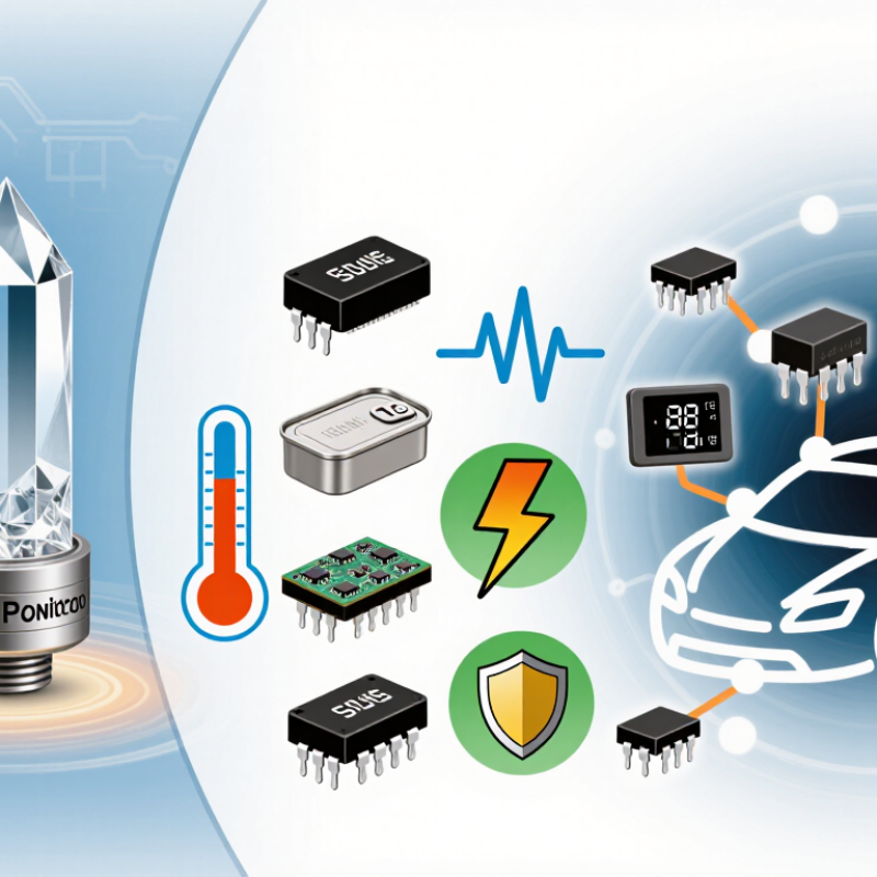
Define the Timing Requirements of the Automotive Application
Before selecting an automotive oscillator, define what the clock must do in the actual system. A camera processor may need low jitter for image sampling, while a body controller may prioritize stable operation across temperature. Record the required frequency, allowable frequency error, startup time, output format, and clock-tree load. Then check the complete timing budget, including drift from temperature, aging, supply variation, and board-level noise. Small errors can accumulate.
Temperature is a practical starting point. AEC-Q100 Rev. J lists operating ranges of −40°C to +125°C for Grade 1 and −40°C to +150°C for Grade 0. Compare the selected grade with measured conditions near the engine bay, inverter, or cabin—not just the vehicle’s advertised ambient range. Leave margin. This is easy to overlook.
Data rates also shape timing needs. IEEE 802.3ch defines automotive Ethernet physical layers at 2.5, 5, and 10 Gb/s, making clock quality and interface compatibility important in high-speed links. Check the receiving device’s tolerance and the oscillator’s jitter specification at the relevant offset frequencies. For safety-related functions, document assumptions and failure responses with the system team; a suitable frequency alone does not establish system safety. Bench testing across temperature and supply corners is useful, though one test setup rarely captures every real installation.
Compare Automotive Oscillator Types and Their Operating Principles
Choosing an automotive oscillator starts with understanding how each type creates a stable clock signal. A quartz crystal oscillator uses the piezoelectric effect: an electrical signal makes a quartz element vibrate at a specific frequency. Its accuracy is generally strong, but temperature shifts and mechanical stress can affect performance. A temperature-compensated crystal oscillator adds circuitry to correct frequency drift. This can help when a module faces cold starts and hot engine-bay conditions.
MEMS oscillators use a tiny silicon resonator driven and measured by electronic circuitry. They can tolerate vibration well and offer compact packaging, though their frequency stability and phase noise depend on the device and application. Ceramic resonators also vibrate mechanically, but typically offer lower precision than quartz.
Less costly. Less precise. That trade-off is easy to underestimate.
Compare operating temperature, vibration exposure, startup time, frequency tolerance, and power needs against the vehicle’s requirements. For example, a timing source near a warm dashboard may face different thermal swings from one mounted beside a powertrain. Check the datasheet’s limits and test the oscillator in the actual circuit.
A part that looks suitable on paper may behave differently under rapid temperature changes; selection is rarely perfect.
Evaluate Frequency, Stability, and Output Specifications
An automotive oscillator should be chosen for the clock it must serve, not by nominal frequency alone. Confirm the processor, sensor, or communication interface’s required frequency and permitted error. A 25 MHz reference may look correct on paper yet drift beyond tolerance across temperature. Check the full operating range, including cold starts and heat soak. Small details matter.
Stability figures need careful reading. Separate initial tolerance from temperature stability, aging, supply sensitivity, and load effects; they describe different error sources. Add worst-case contributions against the system’s timing budget instead of comparing one headline ppm value. If a receiver has little margin, phase noise and jitter can matter as much as average frequency accuracy. The datasheet rarely tells the whole story.
Then match the output to the board. CMOS, clipped-sine, and differential outputs have different voltage, loading, and routing needs. Verify logic thresholds, drive strength, duty cycle, rise time, startup time, and supply voltage. In a noisy vehicle module, check emissions and susceptibility with the actual layout. A stronger output is not automatically better; it can increase power and noise. Leave margin for vibration and temperature, then test the assembled design. Bench conditions can flatter a part, while the installed enclosure changes heat flow.
Assess Temperature, Vibration, and Automotive Qualification Needs
Choosing an automotive oscillator starts with the temperatures it will actually face. A unit near an engine bay may experience heat and cold far beyond the cabin’s range. Check the operating temperature limits, then examine frequency stability across that full span. Include startup behavior, aging, and supply-voltage changes in the review. A nominal frequency alone is not enough. Measure the system’s tolerance before selecting a device; a small frequency shift can affect timing-sensitive communication or control.
Vibration deserves equal attention. Road inputs can stress solder joints and the oscillator’s internal structure, especially on a rigidly mounted board. Review vibration and mechanical-shock test conditions, not just a pass statement. Were the tests relevant to the intended installation? That question is easy to skip. Also consider board support, package size, and placement near connectors or heavy components. Bench testing on a quiet desk will not reveal every issue.
Automotive qualification needs careful verification. Ask for documented qualification status, test summaries, operating limits, and production traceability. Confirm that the qualification applies to the exact part and package, and check which standard fits its component category. Requirements vary by application and customer. A qualified part can still be a poor match if its temperature range or vibration profile falls short. I would leave room for this judgment: datasheets rarely describe every detail of a real vehicle environment, so validate the oscillator in the intended circuit and mounting conditions.
Select and Validate an Oscillator for the Target System
Choosing an automotive oscillator starts with the system’s actual timing needs, not a familiar frequency value. Check required frequency, tolerance, temperature range, supply voltage, and output format against the controller’s specifications. A part rated for a wide temperature range may still drift more than the timing budget allows. The first datasheet choice is rarely the final one. Small differences matter.
Look at startup time, frequency stability, phase noise, and load conditions. For example, a controller may need a stable clock shortly after a cold start, while another circuit may be more sensitive to jitter during data transfer. Check the oscillator’s drive level and the board’s input requirements; mismatches can cause unreliable startup or extra power use. I would also review the layout around the clock input. A long trace beside a switching supply can invite unwanted noise. It is easy to overlook.
Validate the candidate on the target board, not only on paper. Measure frequency and startup behavior at the expected supply limits and across the system’s operating temperatures. A temperature chamber and frequency counter can reveal drift that a room-temperature bench test misses. Test after repeated power cycles, too. Record the setup, probes, and measured results so another engineer can reproduce them. Bench measurements are not the whole story: vibration, nearby switching activity, and enclosure conditions may change performance. If the waveform looks clean but the system still fails intermittently, revisit the measurement method before blaming the oscillator.
How to Choose Automotive Oscillators for Your Application?
Select and validate an oscillator against the target system’s frequency-error budget.
Illustrative budget for a 16 MHz automotive clock: the worst-case contributions add up to 60 ppm, below the example system limit of 75 ppm. Check the selected oscillator’s datasheet across operating temperature, supply voltage, load conditions, and expected service life; these values are example targets, not universal specifications.
